What Is the ESP8266 and Why Does It Matter
The ESP8266 is a low-cost, highly integrated WiFi microcontroller system-on-chip (SoC) developed by Espressif Systems. Released in 2014, it revolutionized the Internet of Things (IoT) landscape by providing built-in WiFi capabilities for under $5 per unit. Unlike traditional microcontrollers such as Arduino Uno, which require external WiFi shields costing $30 or more, the ESP8266 combines a 32-bit Tensilica L106 processor, GPIO pins, SPI, I2C, UART interfaces, and a complete TCP/IP stack on a single chip. This integration enables makers, hobbyists, and professionals to create connected devices—from smart home sensors to remote weather stations—without complex hardware configurations. The chip operates at 80 MHz (overclockable to 160 MHz) with 80 KB of SRAM and up to 16 MB of external flash memory, providing sufficient resources for moderate IoT applications.
ESP8266 Variants: Choosing Your Module
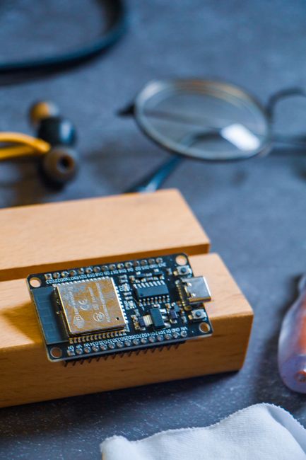
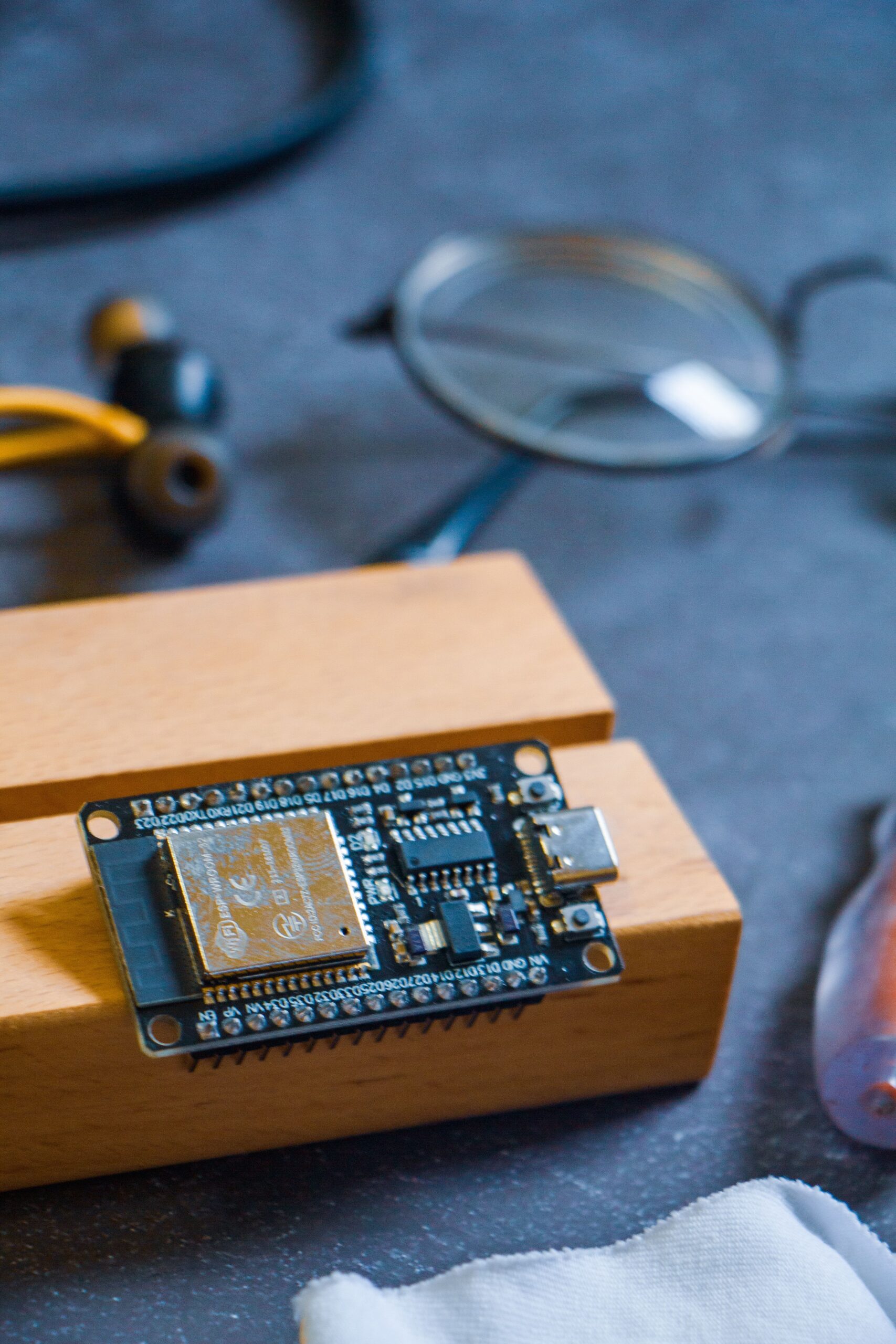
Several ESP8266 modules exist, each tailored to different project scales. The ESP-01 is the most compact, featuring only 2 GPIO pins and a PCB antenna, ideal for simple on/off controls. The ESP-12E/F (commonly seen on NodeMCU boards) exposes 9 GPIO pins, a ceramic antenna, and a metal shield for better signal integrity. The ESP-07 includes an external antenna connector for extended range. For beginners, the NodeMCU v3 or Wemos D1 Mini development boards are recommended—they integrate a USB-to-serial converter, voltage regulation, and breadboard-friendly pin headers, eliminating the need for external programmer hardware. These boards typically cost $3-8 from retailers like AliExpress or Amazon. When sourcing, verify the module’s flash memory: 4 MB (ESP-12E) is standard; 1 MB or 2 MB versions (common in clones) can limit firmware size.
Essential Hardware Setup for First-Time Users
To begin programming the ESP8266, gather these components: a NodeMCU board (or Wemos D1 Mini), a micro-USB cable (data-capable, not charge-only), a breadboard, jumper wires, an LED, and a 220-ohm resistor. Connect the LED’s anode (long leg) through the resistor to GPIO2 (D4 on NodeMCU) and the cathode to GND. This classic “Blink” circuit validates basic operation. Unlike Arduino boards, the ESP8266’s GPIO pins operate at 3.3V logic—connecting 5V peripherals without level shifters will damage the chip. Always power the board through its USB port or a regulated 3.3V supply; the onboard AMS1117 voltage regulator handles USB 5V input but can overheat under heavy loads. For wireless testing, ensure your PC and ESP8266 are on the same WiFi network during initial setup.
Installing the Arduino IDE and ESP8266 Board Support
The Arduino IDE remains the most accessible development environment for ESP8266 beginners. Download version 1.8.19 or later from arduino.cc. Open the IDE, navigate to File > Preferences, and in “Additional Boards Manager URLs,” paste this link: http://arduino.esp8266.com/stable/package_esp8266com_index.json. Then go to Tools > Board > Boards Manager, search “esp8266,” and install “ESP8266 by ESP8266 Community.” This process adds board profiles, libraries, and compiler support—approximately 150 MB of data. After installation, select your specific board: NodeMCU 1.0 (ESP-12E Module) or LOLIN(WEMOS) D1 R2 & Mini from the Tools > Board menu. Set the upload speed to 115200 (default) and Flash Size to “4M (1M SPIFFS).” Connect the board via USB, select the correct COM port (Windows: Device Manager > Ports; macOS/Linux: /dev/cu.usbserial-*). Verify communication by selecting File > Examples > ESP8266 > Blink and clicking Upload. If errors occur, check the cable, drivers (CP2102 or CH340G)—the CH340G often requires manual driver installation on macOS.
Writing Your First WiFi-Connected Sketch
The ESP8266’s hallmark is network connectivity. Below is a minimal sketch that connects to WiFi and reports connection status:
#include
const char* ssid = "YourNetworkName";
const char* password = "YourPassword";

void setup() {
  Serial.begin(115200);
  delay(10);
  Serial.println();
  Serial.print("Connecting to ");
  Serial.println(ssid);

  WiFi.begin(ssid, password);
  while (WiFi.status() != WL_CONNECTED) {
    delay(500);
    Serial.print(".");
  }

  Serial.println("");
  Serial.println("WiFi connected!");
  Serial.print("IP address: ");
  Serial.println(WiFi.localIP());
}

void loop() {
  // Your code here
  delay(1000);
}
Replace SSID and password with your network credentials. After upload, open Serial Monitor (115200 baud) to observe connection progress. The device prints its assigned IP address—note this for later use. This foundational code reveals two critical points: WiFi.begin() is non-blocking after initial handshake, and the ESP8266 consumes ~80 mA during active WiFi transmission vs. 20 mA in deep sleep. For battery-powered projects, always implement sleep modes using WiFi.setSleepMode(WIFI_MODEM_SLEEP).
Common Pitfalls and Troubleshooting
New users frequently encounter these issues:
Failed to connect to COM port – Install CP210x drivers (for NodeMCU v3) or CH340G drivers (for generic clones). On Linux, add user to dialout group. On Windows 10, update drivers via Device Manager > “Update driver” > “Browse my computer” > “Let me pick from a list” > select manufacturer.
Upload errors – Press and hold the FLASH button (NodeMCU) or GPIO0 button while clicking Upload, then release. This puts the chip in programming mode. If persistent, reduce serial baud rate to 9600 or use a capacitor (100 µF) across 3.3V and GND to stabilize power.
WiFi disconnects – WiFiMulti library from ESP8266WiFi.h can handle multiple APs. For weak signals, add an external antenna on ESP-07/12S modules. Avoid using analog pins (A0) near the antenna trace to prevent RF interference.
Serial monitor gibberish – Set baud rate to 115200 (some boards default to 74880). Check Tx/Rx wiring if using FTDI programmer.
Essential Libraries and Next-Level Projects
Beyond basic WiFi, three libraries unlock the ESP8266’s potential:
ESP8266WebServer – Create a simple HTTP server to toggle LEDs via browser. Example: server.on("/on", []{ digitalWrite(LED_BUILTIN, LOW); });
ESP8266HTTPClient – Fetch data from REST APIs. Used with JSON parsing (ArduinoJson library) for weather or cryptocurrency prices.
PubSubClient – MQTT protocol integration for enterprise-level IoT platforms like Home Assistant or AWS IoT.
A practical intermediate project: a DHT22 temperature and humidity sensor publishing data every 30 seconds to an MQTT broker. Connect DHT22 data pin to GPIO4, compile with #include , and publish via client.publish("home/temperature", tempString.c_str()). The ESP8266’s RTC memory also supports time-of-day triggers using NTP synchronization (configTime(-5 * 3600, 3600, "pool.ntp.org")).
Power Management and Real-World Considerations
For battery-operated deployments, optimize power consumption. At 80 mA active, a 2000 mAh LiPo lasts ~25 hours—impractical for continuous use. Implement deep sleep: ESP.deepSleep(10e6) (10 seconds) draws ~10 µA, enabling months of operation on batteries. Use a 18650 cell with an HT7833 LDO regulator for efficiency. The ESP8266’s ADC pin (A0) reads voltages up to 1V only—use a voltage divider (100k:220k) to measure battery levels. For production, consider the ESP8285 (built-in 1 MB flash) or ESP32 for dual-core and Bluetooth Low Energy needs. Always include a 0.1 µF ceramic capacitor near the VCC pin and a 10 µF electrolytic capacitor across power rails to suppress transient spikes that cause resets.
Firmware over-the-air (OTA) updates simplify maintenance: #include enables wireless uploads after initial USB flash. This requires 1.5 MB free flash space. For secure IoT deployments, use WiFi encryption WPA2-Enterprise with ssid and password stored in SPIFFS or EEPROM. Beware that the ESP8266’s WiFi stack is single-threaded—long delays in loop() disrupt packet handling. Use yield() or delay(0) to avoid watchdog timer resets.
Optimizing Performance and Signal Integrity
The ESP8266’s WiFi range approximates 100 meters line-of-sight with the built-in PCB antenna. For weaker signals, position the module high and away from metal enclosures. The chip’s internal antenna’s impedance is 50 ohms—adding a quarter-wave stub (31 mm for 2.4 GHz) on the antenna trace improves reception. GPIO pins can source/sink 12 mA max each; driving LEDs directly is safe, but motors require separate drivers like L298N or MOSFETs. The ADC’s 10-bit resolution (0-1023) provides adequate precision for analog sensors (LDR, potentiometer) but noise is high—average 10 samples with analogRead(A0) for stable readings.
For data-heavy applications, use SPI (up to 80 MHz) over I2C (100-400 kHz). Flash SPIFFS file system enables storing web pages, config files, or credentials without code recompilation. Initialize with SPIFFS.begin() and write files via SPIFFS.open. Note that SPIFFS is read-only during OTA updates—the LittleFS library (recommended for 2.0+) handles concurrent access better.
Community Resources and Further Learning
The ESP8266 ecosystem thrives on community contributions. ESP8266 Community Forum hosts thousands of solved issues. GitHub examples under Espressif’s ESP8266_NONOS_SDK provide reference implementations. For advanced users, explore ESP8266 RTOS SDK with FreeRTOS for multitasking. YouTube channels like Andreas Spiess and DroneBot Workshop offer detailed tutorials. Books such as “Building Wireless Sensor Networks” (Faludi) and “Microcontroller Networking” (Tutorials Point) cover theoretical foundations. Avoid outdated resources from 2014-2016; the ESP8266 SDK and libraries have evolved significantly—always check library documentation dates.
Troubleshooting Checklist for Common Failures
- Chip overheating – Check for 5V on GPIO pins; reduce clock speed to 80 MHz.
- Inconsistent WiFi – Disable
WiFi.setSleepMode(WIFI_NONE_SLEEP)for always-on. - Flash corruption – Erase flash using ESP8266 Sketch Data Upload tool (requires ESP8266FS plugin).
- GPIO output floating – Enable internal pull-ups:
pinMode(5, INPUT_PULLUP). - Stack overflow – Increase stack size in tools menu (default 256 bytes to 512 for complex strings).
- Heartbeat LED not blinking – Verify LED polarity and resistor value; GPIO2 (D4) is inverted (LOW = on).
Selecting Development Tools Beyond Arduino IDE
PlatformIO (Visual Studio Code extension) offers professional-grade features: dependency management, unit testing, and cross-platform builds. The IDE’s platformio.ini file: board = nodemcuv2 and framework = arduino matches NodeMCU. Command-line pio run -t upload speeds iterative development. For debugging, ESP8266 lacks JTAG—use Serial.print() or hook an oscilloscope to TX pin. Logic analyzers (Saleae clones for $10) decode UART, I2C, and SPI bus traffic.
Compliance and Safety Notes
The ESP8266’s 2.4 GHz radio is FCC/CE certified in module form but using an external antenna voids compliance unless tested. For commercial products, use pre-certified modules (ESP-WROOM-02) with proper shielding. Never exceed 3.6V on VIN; the chip’s absolute maximum voltage is 3.6V. Reverse polarity protection via a Schottky diode (1N5817) adds 0.3V drop—use when powered by batteries. For outdoor deployments, conformal coating protects against humidity. Avoid running the chip below -20°C or above 85°C ambient; internal oscillator drift degrades WiFi timing.
Extending Functionality with Sensors and Actuators
The ESP8266 interfaces with countless peripherals. Popular sensor combinations include:
- BME280 (temperature, humidity, pressure) – I2C address 0x76, 3.3V power.
- HC-SR04 ultrasonic distance sensor – needs 5V from NodeMCU VU pin.
- PIR motion sensor (AM312) – 3.3V compatible, output to GPIO5.
- Relay module – optoisolated, trigger with GPIO0, connect common to COM.
- OLED display (SSD1306) – 128×64 pixel, I2C or SPI.
For any external device, verify voltage compatibility. Many sensors tolerate 3.3V but require 5V for accurate readings—use level shifter modules (4-channel bi-directional) for bidirectional lines like I2C SDA/SCL. Power all sensors from the ESP8266’s 3.3V rail only if total current draw stays below 500 mA (NodeMCU regulator limit). For higher loads, use a separate 3.3V/5V supply with common GND.
Final Technical Specifications Reference
- Processor: Tensilica L106 32-bit RISC, 80-160 MHz
- Memory: 50 KB usable SRAM, 80 KB total, 4 MB flash (typical)
- WiFi: 802.11 b/g/n, WPA/WPA2, TCP/IP (uIP or lwIP stack)
- GPIO: 17 total (9 usable on NodeMCU), PWM, ADC (10-bit)
- Interfaces: SPI, I2C, I2S, UART, 1-Wire (software)
- Operating Voltage: 2.5V – 3.6V
- Deep Sleep Current: 10 µA (with RTC timer)
- Active Current: 80 mA (WiFi TX) to 170 mA (peak)
- Dimensions: 24 x 16 mm (ESP-12E module)